.jpg) |
| Figure 1. Ground polygon end result |
Step 1: Prepare Board
 |
| Step 1. Route all pads accordingly |
 |
| Step 2(a). Select Polygon Icon |
.jpg) |
| Step 2(b). Enclose PCB frame with polygon area ( dotted line ) |
Step 3: Check Polygon to see if in correct layer
.jpg) |
| Step 3(a). Select the 'info' icon |
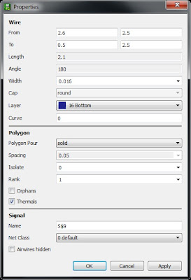
.jpg) |
| Step 3(c). Something like this should appear. Ensure that layer is set to '16 Bottom' |
Step 4. Rename Polygon to GND or Vs
.jpg) |
| Step 4(a). Select 'name' icon |
.jpg) |
| Step 4(b). Something like this should appear |
.jpg) |
| Step 4(c). Change name to 'GND' |
.jpg) |
| Step 5(a). Select 'Ratsnest' Icon to generate polygon |
.jpg) |
| Step 5(b). Polygon generated |
Initial Isolation : 0inch. Plane very close to route and pad
.jpg) |
| Step 6(a). Select 'info' icon again |
.jpg) |
| Step 6(b). Click on the drop-down menu on 'Isolate'. Select a suitable value |
.jpg) |
| Step 6(c). Inspect spacing. Spacing now larger than before and clearer. |
This entry would like to convey a special thanks to James Lewis for his video
No comments:
Post a Comment